What is Flame Arrester
Device fitted to the opening of an enclosure or to the connecting pipework of system of enclosures and whose intended function is to allow flow but prevent the transmission of flame.
- Flame Arrester
Designed to prevent the transmission of explosion propagating at subsonic velocity.
- Deflagration Flame Arrester
Designed to prevent the transmission of explosion propagating at supersonic velocity. (with shock wave)
- Detonation Flame Arrester
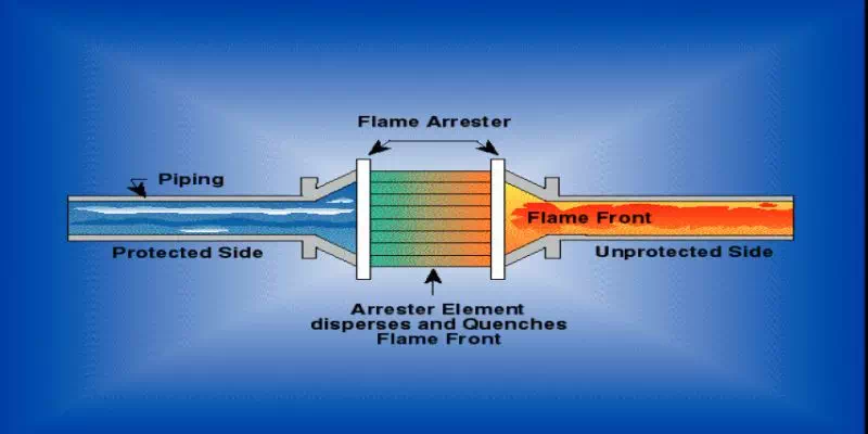
Function
- Flame Barrier
- Flame Holder
- Dissipates Heat
Principle of Flame Arrester
- Dissipates Heat
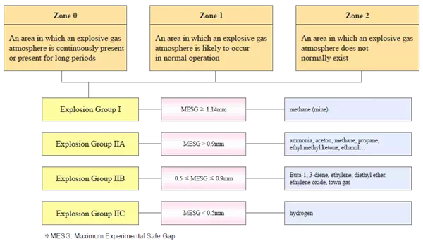
- Gap of Flame Element MESG of Chemical
MESG: Maximum Experimental Safe Gap *For example, MESG of propane is 0.965mm.
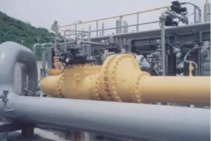
Example of Detonation Flame Arrester
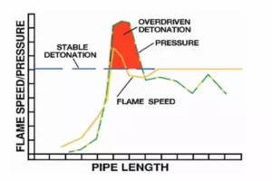
Effect of run-up length on pressure and flame
Basic information for ordering flame arrester
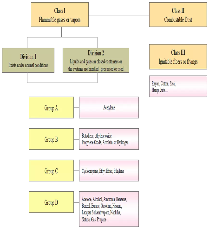
- Kind of mixture of gases or vapors, and their concentrations
- Type (End-of-line/In-line, Deflagration/Detonation)
- Maximum operating pressure
- Normal operating pressure (if possible)
- Operating temperature ranges
- Normal operating temperature (if possible)
- Size and connection (ex, 4” – JIS 10K Raised Face Flange)
- Material of body and flame element
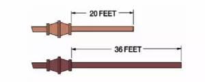
- In case of in-line type, configuration of pipe system and dimensional information (Deflagration Flame arrester should be installed at nearest position from potential ignition source. We recommend it must be installed within 20 times of pipe diameters of the open end of the vent pipe or the potential ignition source.)
- Acceptable pressure drop at flame arrester
- Set pressure, vacuum (for flame arrester with integrated pressure/vacuum relief valve)
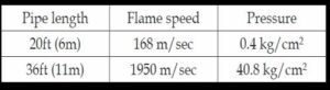
Effect of pipe length on pressure and flame speed
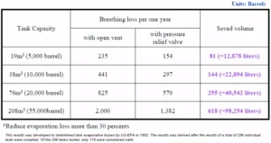
Breathing Loss Comparison Table
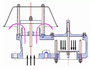
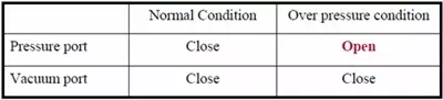
Pressure Relief
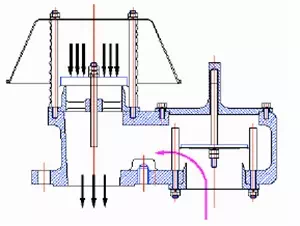
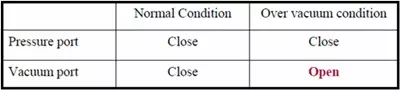
Vacuum Relief
Basic Requirements of Relief Valve
- Anti-corrosion to the handling chemical
- Maximum venting capacity of valve
– Normal venting requirement
– Thermal venting capacity
– Other venting requirements due to chemical reactions, internal or external heat transfer device, etc.
※ These requirement are specified in API 2000 Standard. - Sealing
Causes of Overpressure or Vacuum
- Liquid Movement into or out of a Tank
- Weather Change
- Fire Exposure
- Utility or System Failure
(Internal or External Heat Transfer Device, Venting device etc.,) - Other Circumstances
Basic information for ordering pressure/vacuum relief valve
- Kind of chemical, their concentrations and physical status
- Type (Pressure relief, vacuum relief, pressure and vacuum relief)
- Storage tank capacity
- Design pressure and/or design vacuum of storage tank
- Normal operating pressure/vacuum of storage tank
- Set pressure and/or set vacuum of relief valve
- Maximum filling rate
- Maximum discharging rate
- Insulation thickness of storage tank
- Size and connection (ex, 4” – JIS 10K Raised Face Flange)
- Materials of body, seat, pallet, and diaphragm
- Other information and specification to be considered
Emergency Venting Device
- Emergency Venting for Tank subject to Fire Exposure
- Secondary Safety Device for Emergency
- Large sized and High Capacity
- Access for Maintenance (Large sized model)
General Specification
- Size : 18”, 20”, 24”
- Connection : API 650 or ANSI Class 150lb Flange
- Materials : Carbon Steel / Aluminum / Stainless Steel
- Maximum working Pressure & Set pressure : Determined by
- API Standard 2000
*API: American Petroleum Institute
Emergency venting device (up to 2100mmH2O)
- Size : 4”, 6”, 8”, 10”
- Material : Carbon steel / Aluminum / 304 S.S. / 316 S.S.
- ANSI Class 150lb Flange or Others
Positive pressure gas blanketing helps
![]()
- Prevent outside air, moisture, and other contaminants from entering the storage tank by means of maintaining a constant pressure in the tank. (Enable precise pressure control)
- Protect products (chemicals) in the storage tank from oxidation
- Provides a head pressure above the liquid to reduce evaporation loss, and it helps protect the inside tank corrosion.
- Reduce internal explosion risk
- Provides a function as venting device (Vacuum relief device)
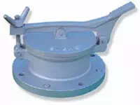
Inert Gas Blanketing Device
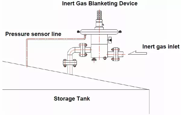
- Maintained a constant pressure
- (Precise pressure control)
- Reduce explosion risk and evaporation loss
- Protect chemical in the storage tank from oxidation
- Venting device (Pressure relief device)
General Specification
![]()
- Set pressure range
- 12.5~200 mmH2O
- 200~500 mmH2O
- Accessories
- Inlet pressure gauge
- Flow indicator and Flow meter
- Flange or NPT, NPT-Female (0.5”~2”)
- Materials
- Body : Stainless Steel